Pitronics: A Toy Claw, a Raspberry Pi, and an Xbox Controller
For Christmas my brother gave me a toy robotic arm kit, a Raspberry Pi 3, and an Xbox controller. The gift was really the project: he studied electrical engineering in college, and the plan was that he would teach me how to design the circuit that connects those three things together. We spent the rest of the holiday on the couch building it.
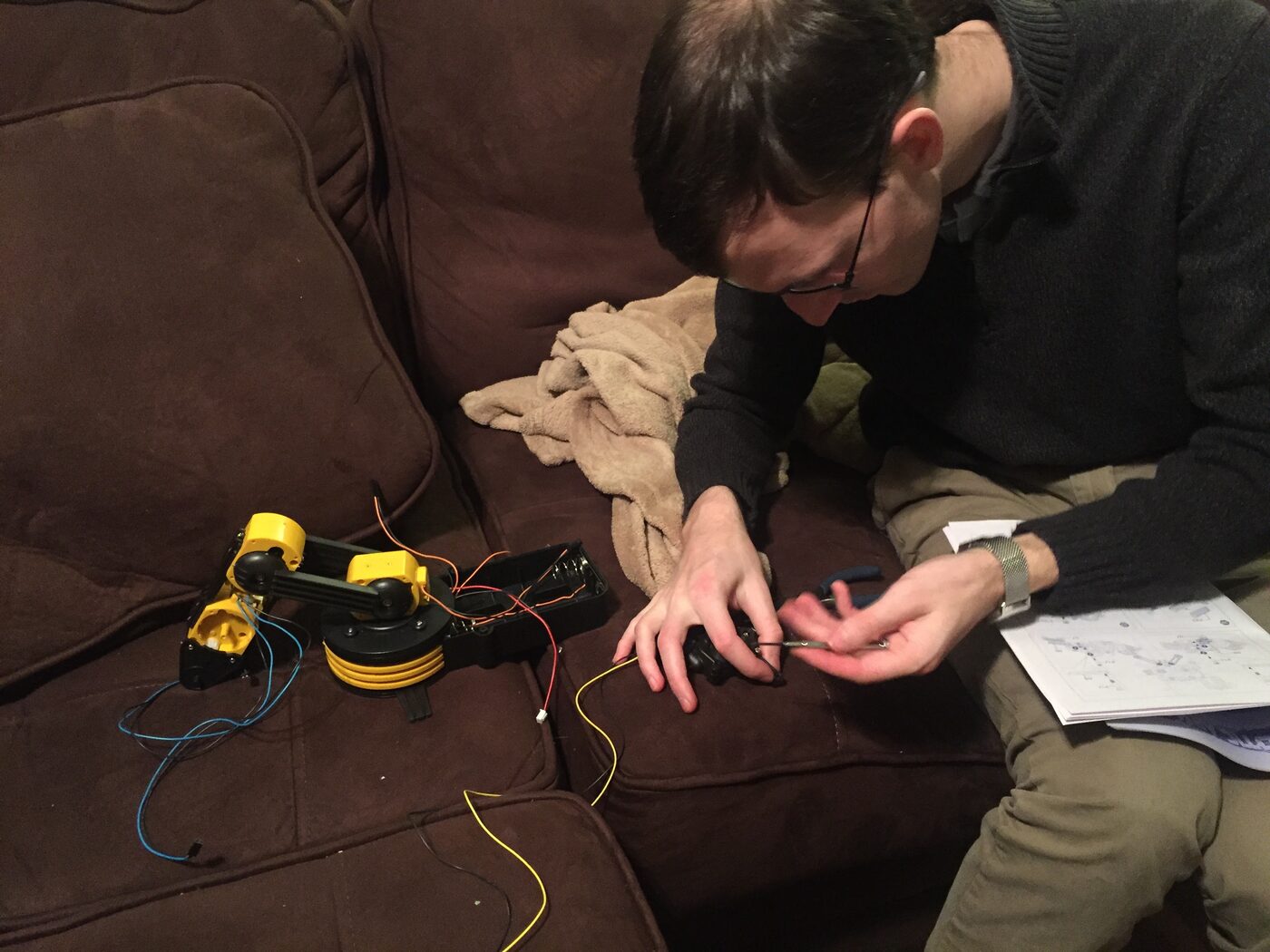
The kit itself is a five-motor arm—gripper, wrist, elbow, shoulder, and a rotating base—plus an LED search light in the head. It ships with a wired controller whose switches connect a battery pack directly to one motor at a time. Assembled and running on its own controller, it looks like this:
The project—pitronics—was to replace that controller with the Pi, and drive the arm from the Xbox controller instead.
The Pi cannot drive a motor
The first thing I learned is that you can’t directly connect the Pi to the robot. A GPIO pin (on the Pi) is a logic signal: 3.3 V, good for a few milliamps, on or off. The arm’s motors want more voltage and current, drawn from the batteries.
So the GPIO pins do not power anything—they decide things, and something else does the work. That something is a bank of relays. Each GPIO pin drives a relay coil through the relay board’s own driver, and the relay’s contacts switch the motor circuit, which stays on the battery’s side of the fence. The two sides share only a common ground and the logic signal.
Each motor gets two relays. One selects polarity, which sets the direction the motor turns; the other completes the circuit, which decides whether it runs at all. That is the whole abstraction, and it maps to about ten lines of Go:
func (m *Motor) SetState(s State) error {
	switch s {
	case State_FORWARD:
		m.direction.High()
		m.onOff.Low()
	case State_BACKWARD:
		m.direction.Low()
		m.onOff.Low()
	case State_STOPPED:
		m.onOff.High()
	}
	return nil
}
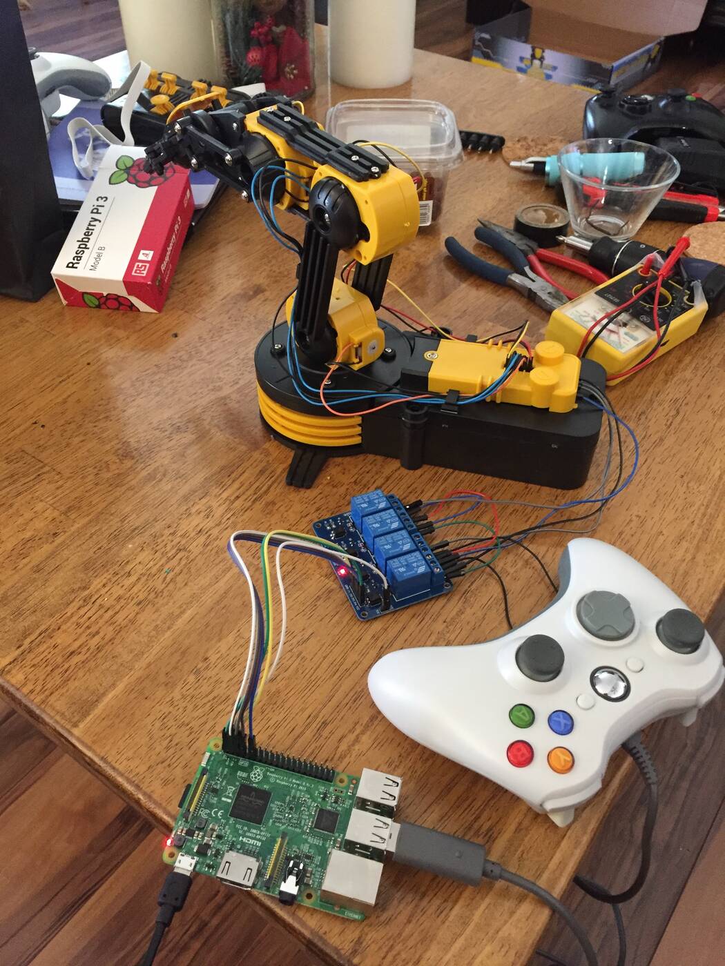
The relay boards are active low, so driving a pin low is what energizes a coil and closes its contacts. Ten motor relays plus one for the search light is eleven GPIO pins, which the Pi has to spare. The bench below started with a single four-channel board driving one joint, wired up next to the multimeter and the pliers:
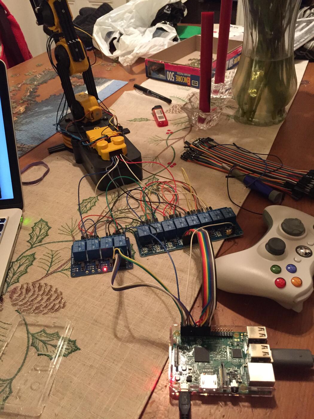
The rest of the motors and the search light came later, once the pattern was working—a four-channel board and an eight-channel board, a ribbon cable to the Pi’s header, and a great many jumper wires:
Most of what my brother taught me is not in the code. Read the manual’s wiring diagram before cutting anything. Check continuity and polarity with the multimeter before you connect two things, not after. Work out on paper which pin does what, because tracing a mistake through a dozen identical wires is much worse than labeling them up front. Watching someone who has done this before work through a circuit is a completely different experience from reading about it.
The software
With the wiring settled, the rest is a small Go program in three layers.
The bottom layer is the one above: a Motor is a pair of rpio pins, and a Claw is five motors plus the LED. Claw.Close() stops every motor and turns off the light.
The middle layer is a gRPC service. clawd runs on the Pi as root, since GPIO access needs /dev/mem, and exposes a single streaming RPC:
service ClawService {
    rpc SetClawState(stream SetClawStateRequest) returns (SetClawStateResponse);
}
A client opens the stream and pushes a new desired state—five motor states and the LED—every time the input changes. Making it a stream rather than a sequence of unary calls has a property I liked more the longer I thought about it: the server’s handler does defer s.Claw.Close(). If the client exits, crashes, or the WiFi drops, the stream ends and every motor stops. The failure mode of a robot arm should be “stop”, and here that is enforced by the transport rather than by remembering to handle it.
The top layer is the controller. jscontroller reads the Xbox controller’s joystick axes and maps each axis to a motor, with a small dead zone so a resting stick does not creep:
m1 := motor.State_STOPPED
if jsState.AxisData[0] < -axisThreshold {
	m1 = motor.State_FORWARD
} else if jsState.AxisData[0] > axisThreshold {
	m1 = motor.State_BACKWARD
}
There is also kbcontroller, a keyboard client built on tcell—arrow keys, WASD, Q and E for the joints, F and R for the search light—which was useful when the controller was not attached and I just wanted to check that a particular relay clicked.
Because the controller is a client, it does not have to be plugged into the Pi. The Pi holds the pins and the arm; anything that can reach it over the network can drive it. The one piece of the wiring that leaked into the software is in clawd, where the motors are registered in the order {m5, m3, m4, m2, m1}: the mapping from joysticks to physical joints was worked out by trying them, and permuting a slice was easier than rewiring the board.
What it led to
The arm is a toy, and the program is a few hundred lines. But it was my introduction to the idea that software can close a physical switch, and to how much careful thinking sits between a GPIO pin and something that moves. A year later I used exactly the same trick—a Pi, a bank of relays, and normally-open contacts bridging a switch—to make a Raspberry Pi play a handheld Yahtzee game by pressing its buttons. That project would not have occurred to me if my brother had not spent a holiday teaching me how the relays work.
Source is on GitHub.